


Talk:Subtractor
Add topic | This  level-5 vital article is rated Start-class on Wikipedia's content assessment scale. level-5 vital article is rated Start-class on Wikipedia's content assessment scale.It is of interest to the following WikiProjects: | ||||||||||
| |||||||||||

Can the Subtracter (electronics) be explained with circuits and truth tables the same way as the Adder (electronics)(http://en.wikipedia.org/wiki/Full_adder)?
- a subtractor is basically just an adder with one input inverted and the first carry in set to 1 rather than 0.
Full Subtractor
[edit]the truth table for full subtractor is not correct; read this => http://www.doc.ic.ac.uk/~dfg/hardware/HardwareLecture13.pdf 60.48.175.38 (talk) 18:57, 26 September 2011 (UTC)
Note, the full substractor graphic is wrong. The first inversor goes in the A imput. If the subtrahend is 0 and the minuend is 1, it triggers the borrow out. — Preceding unsigned comment added by Mbertelotti (talk • contribs) 20:42, 22 April 2013 (UTC)
Half subtractor diagram
[edit]The diagram should be replaced such that the X input is the minuend and Y is the subtrahend. Doing it this way would make the diagram consistent with the article and the following explanation unnecessary:
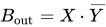
An important point worth mentioning is that the half subtractor diagram aside implements and not since on the diagram is given by
- .
This is an important distinction to make since subtraction itself is not commutative, but the difference bit is calculated using an XOR gate which is commutative.



We could still have a footnote that says whichever input is inverted is the minuend. --Usability (talk) 07:40, 1 November 2015 (UTC)