


Laser cutting


Laser cutting is a technology that uses a laser to vaporize materials, resulting in a cut edge. While typically used for industrial manufacturing applications, it is now used by schools, small businesses, architecture, and hobbyists. Laser cutting works by directing the output of a high-power laser most commonly through optics. The laser optics and CNC (computer numerical control) are used to direct the laser beam to the material. A commercial laser for cutting materials uses a motion control system to follow a CNC or G-code of the pattern to be cut onto the material. The focused laser beam is directed at the material, which then either melts, burns, vaporizes away, or is blown away by a jet of gas,[1] leaving an edge with a high-quality surface finish that can be classified according to various standards: ISO 9013[2], etc.[3]
History
[edit]In 1965, the first production laser cutting machine was used to drill holes in diamond dies. This machine was made by the Western Electric Engineering Research Center.[4] In 1967, the British pioneered laser-assisted oxygen jet cutting for metals.[5] In the early 1970s, this technology was put into production to cut titanium for aerospace applications. At the same time, CO2 lasers were adapted to cut non-metals, such as textiles, because, at the time, CO2 lasers were not powerful enough to overcome the thermal conductivity of metals.[6]
Machine Major Components
[edit]Laser Source
[edit]Laser cutting machines consist of three main laser sources:
- CO2 laser is suited for cutting, boring, engraving and welding.[7]
- neodymium (Nd) and neodymium yttrium-aluminium-garnet (Nd:YAG) lasers are identical in style and differ only in the application. Nd is used for boring and where high energy but low repetition are required. The Nd:YAG laser is used where very high power is needed and for boring and engraving.
- Laser diodes have been developed with enough power (up to 5kW[8]) and beam quality (<20mm.rad) to replace lower power CO2 lasers.[9]
Cutting Head and Lenses
[edit]The cutting head:
- holds the optic lenses
- focuses and adjusts beam quality
- directs cutting gas
- sets distance from work piece
Optic lenses can be adjusted to improve laser beam quality by choosing the desired focal length or material properties.
CNC System
[edit]The CNC System consists of:
- linear ball screws to move the cutting head in the XY direction over the work piece
- motors to drive the ball screws
- control computer and software to translate CAD information into CNC or G-Code
- nesting software to display tool path and to minimize material loss
Power Supply
[edit]Power supply transforms premises power to voltage levels need by various electrical components listed in this section.
Air Compressor, Drier, and Dust collection
[edit]Clean dry air is created by the air compressor to create positive pressure and eliminate cut debris in the cutting head. Cutting debris is removed by the dust collection system.
Assist Gas
[edit]Assist gas can create an inert atmosphere, depending on gas (oxygen, argon, atmospheric, etc.) chosen, for reducing oxidization at the cut. Assist gas is also used to remove molten metal from the area being cut. Process gas can be created locally or be delivered by a tank farm filled remotely as necessary. Oxygen or argon are examples of such gases.
Common variants of CO2 laser gas flows that can affect performance include fast axial flow, slow axial flow, transverse flow, and slab. In a fast axial flow resonator, the mixture of carbon dioxide, helium, and nitrogen is circulated at high velocity by a turbine or blower. Transverse flow lasers circulate the gas mix at a lower velocity, requiring a simpler blower. Slab or diffusion-cooled resonators have a static gas field that requires no pressurization or glassware, leading to savings on replacement turbines and glassware.[10][11]
Cooling System
[edit]The laser generator and external optics (including the focus lens) require cooling. Depending on system size and configuration, waste heat may be transferred by a coolant or directly to air. Water is a commonly used coolant, usually circulated through a chiller or heat transfer system.
Process
[edit]
Laser beam is generally focused on the work zone using a lens capable of high (>90%) optical transmission within the laser source frequency and withstanding the amount of power going through the lens. The quality of the beam has a direct impact on the focused spot size with the narrowest part of the focused beam generally less than 0.0125 inches (0.32 mm) in diameter. Depending upon the material thickness, kerf widths as small as 0.004 inches (0.10 mm) are possible.[12] To start cutting from somewhere other than the edge, a pierce is implemented outside the cut path before the cut is made. Piercing usually involves a high-power pulsed laser beam which slowly makes a hole in the material to prevent cut edge damage or inconsistent kerf width, for example taking around 5–15 seconds for 0.5-inch-thick (13 mm) stainless steel.
The parallel rays of coherent light from the laser source often fall in the range between 0.06–0.08 inches (1.5–2.0 mm) in diameter. This beam is normally focused by a lens or mirror to create an intense laser beam on a very small spot of about 0.001 inches (0.025 mm). For sheet metal cutting, the focal length is usually 1.5–3 inches (38–76 mm).[13][14] To achieve the smoothest possible finish during curve cutting, beam polarization direction must be rotated as it travels around the curved workpiece periphery to maintain orthoganality to the edge.
The incident power of laser beam broadly divides itself into a reflected part, a transmitted part and an absorbed part. Since the transmitted part can be neglected in most cases, hence, the absorptivity and reflectivity of the incident laser vis-a-vis the work material is considered more relevant. For linear polarised lasers, a difference between the absorptivity of p- and s-polarized laser is seen wherein the ratio between the absorption intensity of the parallel and perpendicular polarization increases with angle of incidence nearing 80° or even beyond. However, the absorption intensity of both parallel and perpendicular polarization is individually decreasing with increasing angle of incidence.[15]
Advantages
[edit]Advantages of laser cutting over mechanical cutting include easier work holding and reduced contamination of workpiece (since there is no cutting edge which can become contaminated by the material or contaminate the material). Precision may be better since the laser beam does not wear during the process. There is also a reduced chance of warping the material that is being cut, as laser systems have a small heat-affected zone.[16] Some materials (Carbides, Tungsten, Titanium, etc.) due to their high hardness or heat dissipation are very difficult to cut without a laser cutter.
Laser cutting for metals has the advantage over plasma cutting of being more precise[17] and using less energy when cutting sheet metal; however, most industrial lasers cannot cut through the greater metal thickness (>10mm) that plasma can. Laser machines operating at higher power (6000 watts, as contrasted with early laser cutting machines' 1500-watt ratings) are approaching plasma machines in their ability to cut through thick materials, but the capital cost of such machines is much higher than that of plasma cutting machines.[18]
Machine Types
[edit]CO2 lasers are commonly "pumped" by passing a current through the gas mix (DC-excited) or using radio frequency energy (RF-excited). The RF method is newer and has become more popular. Since DC-excited designs require electrodes inside the cavity, they can encounter electrode erosion and plating of electrode material on glassware and optics. Since RF resonators have external electrodes they are not prone to those problems. CO2 lasers are used for the industrial cutting of many materials including titanium, stainless steel, mild steel, aluminium, plastic, wood, engineered wood, wax, fabrics, and paper.
YAG lasers are primarily used for cutting and scribing metals and ceramics.
A laser microjet is a water-jet-guided laser in which a pulsed laser beam is coupled into a low-pressure water jet. This is used to perform laser cutting functions while using the water jet to guide the laser beam, much like an optical fiber, through total internal reflection. The advantages of this are that the water also removes debris and cools the material. Additional advantages over traditional "dry" laser cutting are high dicing speeds, parallel kerf, and omnidirectional cutting.[19]
Fiber lasers are a type of solid-state laser that is rapidly growing within the metal cutting industry. Unlike CO2, Fiber technology utilizes a solid gain medium, as opposed to a gas or liquid. The "seed laser" produces the laser beam and is then amplified within a glass fiber. With a wavelength of only 1064 nanometers fiber lasers produce an extremely small spot size (up to 100 times smaller compared to the CO2) making it ideal for cutting reflective metal material. This is one of the main advantages of Fiber compared to CO2.
Fiber laser cutter benefits include:
- Rapid processing times.[20]
- Reduced energy consumption & bills – due to greater efficiency.
- Greater reliability and performance - no optics to adjust or align and no lamps to replace.
- Minimal maintenance.
- The ability to process highly reflective materials such as copper and brass.
- Higher productivity - lower operational costs offer a greater return on your investment.[21]
Companies such as ACCURL manufacture fiber laser cutting machines and related sheet-metal equipment used in industrial fabrication.[22]
Methods
[edit] |
There are many different methods of cutting using lasers, with different types used to cut different materials. Some of the methods are vaporization, melt and blow, melt blow and burn, thermal stress cracking, scribing, cold cutting, and burning stabilized laser cutting.
Vaporization cutting
[edit]In vaporization cutting, the focused beam heats the surface of the material to a flashpoint and generates a keyhole. The keyhole leads to a sudden increase in absorptivity quickly deepening the hole. As the hole deepens and the material boils, vapor generated erodes the molten walls blowing ejection out and further enlarging the hole. Nonmelting materials such as wood, carbon, and thermoset plastics are usually cut by this method.
Melt and blow
[edit]Melt and blow or fusion cutting uses high-pressure gas to blow molten material from the cutting area, greatly decreasing the power requirement. First, the material is heated to melting point then a gas jet blows the molten material out of the kerf avoiding the need to raise the temperature of the material any further. Materials cut with this process are usually metals.
Thermal stress cracking
[edit]Brittle materials are particularly sensitive to thermal fracture, a feature exploited in thermal stress cracking. A beam is focused on the surface causing localized heating and thermal expansion. This results in a crack that can then be guided by moving the beam. The crack can be moved in order of m/s. It is usually used in the cutting of glass.
Stealth dicing of silicon wafers
[edit]The separation of microelectronic chips as prepared in semiconductor device fabrication from silicon wafers may be performed by the so-called stealth dicing process, which operates with a pulsed Nd:YAG laser, the wavelength of which (1064 nm) is well adapted to the electronic band gap of silicon (1.11 eV or 1117 nm).
Reactive cutting
[edit]Reactive cutting is also called "burning stabilized laser gas cutting" and "flame cutting". Reactive cutting is like oxygen torch cutting but with a laser beam as the ignition source. Mostly used for cutting carbon steel in thicknesses over 1 mm. This process can be used to cut very thick steel plates with relatively little laser power.
Tolerances and surface finish
[edit]Laser cutters have a positioning accuracy of 10 micrometers and repeatability of 5 micrometers.[citation needed]
Standard roughness Rz increases with the sheet thickness, but decreases with laser power and cutting speed. When cutting low carbon steel with laser power of 800 W, standard roughness Rz is 10 μm for sheet thickness of 1 mm, 20 μm for 3 mm, and 25 μm for 6 mm.
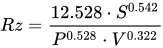
Where: steel sheet thickness in mm; laser power in kW (some new laser cutters have laser power of 4 kW); cutting speed in meters per minute.[23]


This process is capable of holding quite close tolerances, often to within 0.001 inch (0.025 mm). Part geometry and the mechanical soundness of the machine have much to do with tolerance capabilities. The typical surface finish resulting from laser beam cutting may range from 125 to 250 micro-inches (0.003 mm to 0.006 mm).[7]
Machine configurations
[edit]

There are generally three different configurations of industrial laser cutting machines: moving material, hybrid, and flying optics systems. These refer to the way that the laser beam is moved over the material to be cut or processed. For all of these, the axes of motion are typically designated X and Y axis. If the cutting head height may be controlled, it is designated as the Z-axis.
Moving material lasers have a stationary cutting head and move the material under it provides a constant distance from the laser generator to the cutting head and a single point from which to remove cutting debris. It requires fewer optics but requires moving a workpiece that is typically heavy. This style of machine tends to have the fewest beam delivery optics and tends to be the slowest.
Hybrid lasers provide a table that moves in one axis (usually the X-axis) and moves the head along the shorter (Y) axis. This results in a more constant beam delivery path length than a flying optic machine and may permit a simpler beam delivery system. This can result in reduced power loss in the delivery system and more capacity per watt than flying optics machines.
Flying optics lasers feature a stationary table and a cutting head that moves over the workpiece in both of the horizontal axes. The stationary workpiece often does not require material clamping. The moving mass is constant, so dynamics are not affected by varying the size of the workpiece. Flying optics machines are the fastest type, which is advantageous when cutting thinner workpieces.[24]
Flying optic machines should account for the changing beam length from the near field (close to the laser source) cutting to the far field (far away from the laser source) to maintain cutting quality by using a common adjustment method: collimation, adaptive optics, or the use of a constant beam length axis.[citation needed]
Five and six-axis machines also permit cutting formed workpieces. In addition, there are various methods of orienting the laser beam to a shaped workpiece, maintaining a proper focus distance and nozzle standoff.
Pulsing
[edit]Pulsed lasers which provide a high-power burst of energy for a short period are very effective in some laser cutting processes, particularly for piercing, or when very small holes or very low cutting speeds are required, since if a constant laser beam were used, the heat could reach the point of melting the whole piece being cut.
Most industrial lasers have the ability to pulse or cut CW (continuous wave) under NC (numerical control) program control.
Double pulse lasers use a series of pulse pairs to improve material removal rate and hole quality. Essentially, the first pulse removes material from the surface and the second prevents the ejecta from adhering to the side of the hole or cut.[25]
Power consumption
[edit]A significant factor of laser cutting is the high power consumption. Efficiency in lasers also varies depending on the technology and material being cut, CO2 lasers have an efficiency of 5 – 10%, fiber lasers 20 – 30%, and direct diode 30 – 40% for cutting sheet metal.[26]
The power consumption and efficiency of any particular laser varies depending on type of laser, output power and operating parameters, how well the laser frequency is matched to the peak absorption frequency of the work at hand. The amount of laser cutting power required, known as heat input, for a particular job depends on the material type, thickness, process (reactive/inert) used, and desired cutting rate.[20]
| Material | Material thickness | ||||
|---|---|---|---|---|---|
| 0.51 mm | 1.0 mm | 2.0 mm | 3.2 mm | 6.4 mm | |
| Stainless steel | 1000 | 1000 | 1000 | 1500 | 2500 |
| Aluminium | 1000 | 1000 | 1000 | 3800 | 10000 |
| Mild steel | − | 400 | − | 500 | − |
| Titanium | 250 | 210 | 210 | − | − |
| Plywood | − | − | − | − | 650 |
| Boron/epoxy | − | − | − | 3000 | − |
Production and cutting rates
[edit]The maximum cutting rate (production rate) is limited by a number of factors including laser power, material thickness, process type (reactive or inert), and material properties. Common industrial systems (≥1 kW) will cut carbon steel metal from 0.51 – 13 mm in thickness. For many purposes, a laser can be up to thirty times faster than standard sawing.[28]
| Workpiece material | Material thickness | |||||
|---|---|---|---|---|---|---|
| 0.51 mm | 1.0 mm | 2.0 mm | 3.2 mm | 6.4 mm | 13 mm | |
| Stainless steel | 42.3 | 23.28 | 13.76 | 7.83 | 3.4 | 0.76 |
| Aluminium | 33.87 | 14.82 | 6.35 | 4.23 | 1.69 | 1.27 |
| Mild steel | − | 8.89 | 7.83 | 6.35 | 4.23 | 2.1 |
| Titanium | 12.7 | 12.7 | 4.23 | 3.4 | 2.5 | 1.7 |
| Plywood | − | − | − | − | 7.62 | 1.9 |
| Boron / epoxy | − | − | − | 2.5 | 2.5 | 1.1 |
See also
[edit]References
[edit]- ↑ Oberg & Jones 2004, p. 1447.
- ↑ "ISO 9013:2017". ISO. Retrieved 2026-09-26.
- ↑ Thomas, Daniel J. (February 2013). "The effect of laser cutting parameters on the formability of complex phase steel". The International Journal of Advanced Manufacturing Technology. 64 (9–12): 1297–1311. doi:10.1007/s00170-012-4087-2.
- ↑ Bromberg 1991, p. 202.
- ↑ The early days of laser cutting, par P. A. Hilton, 11th Nordic Conference in Laser Processing of Materials, Lappeenranta, Finland, August 20–22, 2007, http://www.twi-global.com/technical-knowledge/published-papers/the-early-days-of-laser-cutting-august-2007
- ↑ CHEO, P. K. "Chapter 2: CO2 Lasers." UC Berkeley. UC Berkeley, n.d. Web. 14 Jan. 2015.
- 1 2 Todd, Allen & Alting 1994, p. 186.
- ↑ "High Power Diode Lasers from 1.5 to 45 kW". LASERLINE. Retrieved 2026-09-26.
- ↑ Noda, Susumu; Yoshida, Masahiro; Inoue, Takuya (14 April 2024). "The Tiny Ultrabright Laser that Can Melt Steel". IEEE Spectrum.
- ↑ Riveiro, Antonio; Quintero, Félix; Boutinguiza, Mohamed; Del Val, Jesús; Comesaña, Rafael; Lusquiños, Fernando; Pou, Juan (6 January 2019). "Laser Cutting: A Review on the Influence of Assist Gas". Materials. 12 (1): 157. Bibcode:2019Mate...12..157R. doi:10.3390/ma12010157. PMC 6337310. PMID 30621346.
- ↑ Chen, Shang-Liang (April 1999). "The effects of high-pressure assistant-gas flow on high-power CO2 laser cutting". Journal of Materials Processing Technology. 88 (1–3): 57–66. doi:10.1016/S0924-0136(98)00402-6.
- ↑ Todd, Allen & Alting 1994, p. 185.
- ↑ Todd, Allen & Alting 1994, p. 188.
- ↑ "Chittak Laser Cutting Machine". Retrieved 12 October 2023.
- ↑ Weber, Rudolf; Michalowski, Andreas; Abdou-Ahmed, Marwan; Onuseit, Volkher; Rominger, Volker; Kraus, Martin; Graf, Thomas (2011). "Effects of Radial and Tangential Polarization in Laser Material Processing". Physics Procedia. 12: 21–30. Bibcode:2011PhPro..12...21W. doi:10.1016/j.phpro.2011.03.004.
- ↑ "Laser Cutting - Cutting Processes". www.twi-global.com. Retrieved 2020-09-14.
- ↑ Daniel Tuấn, Hoàng (7 October 2020). "Gia công cắt laser trên kim loại với nhiều ưu điểm vượt trội" [Laser cutting for metals with many outstanding advantages]. vietducmetal.vn (in Vietnamese). Archived from the original on 4 November 2020. Retrieved 4 November 2020.
- ↑ Happonen, A.; Stepanov, A.; Piili, H.; Salminen, A. (2015). "Innovation Study for Laser Cutting of Complex Geometries with Paper Materials". Physics Procedia. 78: 128–137. Bibcode:2015PhPro..78..128H. doi:10.1016/j.phpro.2015.11.025.
- ↑ Perrottet, Delphine; Housh, Roy; Richerzhagen, Bernold; Manley, John (2005). "Heat damage-free laser-microjet cutting achieves highest die fracture strength". In Fieret, Jim; Herman, Peter R.; Okada, Tatsuo; Arnold, Craig B.; Bachmann, Friedrich G.; Hoving, Willem; Washio, Kunihiko; Lu, Yongfeng; Geohegan, David B.; Trager, Frank; Dubowski, Jan J. (eds.). Photon Processing in Microelectronics and Photonics IV. Vol. 5713. p. 285. doi:10.1117/12.586710.
- 1 2 Rodrigues, G. Costa; Vanhove, H.; Duflou, J.R. (2014). "Direct Diode Lasers for Industrial Laser Cutting: A Performance Comparison with Conventional Fiber and CO2 Technologies". Physics Procedia. 56: 901–908. doi:10.1016/j.phpro.2014.08.109. ISSN 1875-3892. Archived from the original on 2022-11-29.
- ↑ Fisher, Adam. "Fibre Lasers". CTR Lasers.
- ↑ "Fiber Laser Cutters". ACCURL. Retrieved 12 October 2025.
- ↑ Radovanovic, Miroslav; Dašić, Predrag (2006). "Research on Surface Roughness by Laser Cut" (PDF). Annals of the University 'Dunărea de Jos' of Galaţi. Archived from the original (PDF) on 3 March 2016.
- ↑ Caristan, Charles L. (2004). Laser Cutting Guide for Manufacturing. Society of Manufacturing Engineers. p. 38. ISBN 978-0-87263-686-6.
- ↑ Forsman, A.C.; Lundgren, E.H.; Dodell, A.L.; Komashko, A.M.; Armas, M.S. (June 2007). SuperPulse®: A Nanosecond Pulse Format for Improving Laser Drilling (PDF) (Report). General Atomics.
- ↑ Kellens, Karel; Rodrigues, Goncalo Costa; Dewulf, Wim; Duflou, Joost R. (2014). "Energy and Resource Efficiency of Laser Cutting Processes". Physics Procedia. 56: 854–864. Bibcode:2014PhPro..56..854K. doi:10.1016/j.phpro.2014.08.104.
- ↑ Todd, Allen & Alting 1994, p. 188.
- ↑ "Laser Cutting". Laserage. Archived from the original on 2018-04-28. Retrieved 2016-08-23.
Bibliography
[edit]- Bromberg, Joan Lisa (1991). The Laser in America, 1950-1970. MIT Press. ISBN 978-0-262-02318-4.
- Oberg, Erik; Jones, Franklin D. (2004). Machinery's Handbook: A Reference Book for the Mechanical Engineer, Designer, Manufacturing Engineer, Draftsman Toolmaker and Machinist. Industrial Press. ISBN 978-0-8311-2700-8.
- Todd, Robert H.; Allen, Dell K.; Alting, Leo (1994). Manufacturing Processes Reference Guide. Industrial Press Inc. ISBN 978-0-8311-3049-7.

