


NAND logic
The NAND Boolean function has the property of functional completeness. This means that any Boolean expression can be re-expressed by an equivalent expression utilizing only NAND operations. For example, the function NOT(x) may be equivalently expressed as NAND(x,x). In the field of digital electronic circuits, this implies that it is possible to implement any Boolean function using just NAND gates.
The mathematical proof for this was published by Henry M. Sheffer in 1913 in the Transactions of the American Mathematical Society (Sheffer 1913). A similar case applies to the NOR function, and this is referred to as NOR logic.
NAND
[edit]A NAND gate is an inverted AND gate. It has the following truth table:
 | |
| Q = A NAND B | |
| Input A | Input B | Output Q |
|---|---|---|
| 0 | 0 | 1 |
| 0 | 1 | 1 |
| 1 | 0 | 1 |
| 1 | 1 | 0 |

In CMOS logic, if both of the A and B inputs are high, then both the NMOS transistors (bottom half of the diagram) will conduct, neither of the PMOS transistors (top half) will conduct, and a conductive path will be established between the output and Vss (ground), bringing the output low. If both of the A and B inputs are low, then neither of the NMOS transistors will conduct, while both of the PMOS transistors will conduct, establishing a conductive path between the output and Vdd (voltage source), bringing the output high. If either of the A or B inputs is low, one of the NMOS transistors will not conduct, one of the PMOS transistors will, and a conductive path will be established between the output and Vdd (voltage source), bringing the output high. As the only configuration of the two inputs that results in a low output is when both are high, this circuit implements a NAND (NOT AND) logic gate.
Making other gates by using NAND gates
[edit]A NAND gate is a universal gate, meaning that any other gate can be represented as a combination of NAND gates.
NOT
[edit]A NOT gate is made by joining the inputs of a NAND gate together. Since a NAND gate is equivalent to an AND gate followed by a NOT gate, joining the inputs of a NAND gate leaves only the NOT gate.
| Desired NOT Gate | NAND Construction |
|---|---|
 |  |
| Q = NOT( A ) | = A NAND A |
| Input A | Output Q |
|---|---|
| 0 | 1 |
| 1 | 0 |
AND
[edit]An AND gate is made by inverting the output of a NAND gate as shown below.
| Desired AND Gate | NAND Construction |
|---|---|
 |  |
| Q = A AND B | = ( A NAND B ) NAND ( A NAND B ) |
| Input A | Input B | Output Q |
|---|---|---|
| 0 | 0 | 0 |
| 0 | 1 | 0 |
| 1 | 0 | 0 |
| 1 | 1 | 1 |
OR
[edit]If the truth table for a NAND gate is examined or by applying De Morgan's laws, it can be seen that if any of the inputs are 0, then the output will be 1. To be an OR gate, however, the output must be 1 if any input is 1. Therefore, if the inputs are inverted, any high input will trigger a high output.
| Desired OR Gate | NAND Construction |
|---|---|
 |  |
| Q = A OR B | = ( A NAND A ) NAND ( B NAND B ) |
| Input A | Input B | Output Q |
|---|---|---|
| 0 | 0 | 0 |
| 0 | 1 | 1 |
| 1 | 0 | 1 |
| 1 | 1 | 1 |
NOR
[edit]A NOR gate is an OR gate with an inverted output. Output is high when neither input A nor input B is high.
| Desired NOR Gate | NAND Construction |
|---|---|
 |  |
| Q = A NOR B | = [ ( A NAND A ) NAND ( B NAND B ) ] NAND [ ( A NAND A ) NAND ( B NAND B ) ] |
| Input A | Input B | Output Q |
|---|---|---|
| 0 | 0 | 1 |
| 0 | 1 | 0 |
| 1 | 0 | 0 |
| 1 | 1 | 0 |
XOR
[edit]An XOR gate is made by connecting four NAND gates as shown below. This construction entails a propagation delay three times that of a single NAND gate.
| Desired XOR Gate | NAND Construction |
|---|---|
 |  |
| Q = A XOR B | = [ A NAND ( A NAND B ) ] NAND [ B NAND ( A NAND B ) ] |
| Input A | Input B | Output Q |
|---|---|---|
| 0 | 0 | 0 |
| 0 | 1 | 1 |
| 1 | 0 | 1 |
| 1 | 1 | 0 |
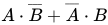
Alternatively, an XOR gate is made by considering the disjunctive normal form , noting from de Morgan's law that a NAND gate is an inverted-input OR gate. This construction uses five gates instead of four.
| Desired Gate | NAND Construction |
|---|---|
|  |
| Q = A XOR B | = [ B NAND ( A NAND A ) ] NAND [ A NAND ( B NAND B ) ] |
XNOR
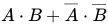
[edit]An XNOR gate is made by considering the disjunctive normal form , noting from de Morgan's law that a NAND gate is an inverted-input OR gate. This construction entails a propagation delay three times that of a single NAND gate and uses five gates.
| Desired XNOR Gate | NAND Construction |
|---|---|
 |  |
| Q = A XNOR B | = [ ( A NAND A ) NAND ( B NAND B ) ] NAND ( A NAND B ) |
| Input A | Input B | Output Q |
|---|---|---|
| 0 | 0 | 1 |
| 0 | 1 | 0 |
| 1 | 0 | 0 |
| 1 | 1 | 1 |
Alternatively, the 4-gate version of the XOR gate can be used with an inverter. This construction has a propagation delay four times (instead of three times) that of a single NAND gate.
| Desired Gate | NAND Construction |
|---|---|
|  |
| Q = A XNOR B | = { [ A NAND ( A NAND B ) ] NAND [ B NAND ( A NAND B ) ] } NAND { [ A NAND ( A NAND B ) ] NAND [ B NAND ( A NAND B ) ] } |
MUX
[edit]A multiplexer or a MUX gate is a three-input gate that uses one of the inputs, called the selector bit, to select one of the other two inputs, called data bits, and outputs only the selected data bit.[1]
| Desired MUX Gate | NAND Construction |
|---|---|
 | |
| Q = [ A AND NOT( S ) ] OR ( B AND S ) | = [ A NAND ( S NAND S ) ] NAND ( B NAND S ) |
| Input A | Input B | Select | Output Q |
|---|---|---|---|
| 0 | 0 | 0 | 0 |
| 0 | 1 | 0 | 0 |
| 1 | 0 | 0 | 1 |
| 1 | 1 | 0 | 1 |
| 0 | 0 | 1 | 0 |
| 0 | 1 | 1 | 1 |
| 1 | 0 | 1 | 0 |
| 1 | 1 | 1 | 1 |
DEMUX
[edit]A demultiplexer performs the opposite function of a multiplexer: It takes a single input and channels it to one of two possible outputs according to a selector bit that specifies which output to choose.[1]
| Desired DEMUX Gate | NAND Construction |
|---|---|
|
| |

| Input | Select | Output A | Output B |
|---|---|---|---|
| 0 | 0 | 0 | 0 |
| 1 | 0 | 1 | 0 |
| 0 | 1 | 0 | 0 |
| 1 | 1 | 0 | 1 |
See also
[edit]- CMOS transistor structures and chip deposition geometries that produce NAND logic elements
- Functional completeness
- NOR logic – like NAND gates, NOR gates are also universal gates
- Sheffer stroke – other name
References
[edit]- 1 2 Nisan, Noam; Schocken, Shimon (2005). "1. Boolean Logic". From NAND to Tetris: Building a Modern Computer from First Principles (PDF). The MIT Press. Archived from the original (PDF) on 2017-01-10.
- Lancaster, Don (1974). TTL Cookbook (1st ed.). Indianapolis, IN: Howard W Sams. pp. 126–135. ISBN 0-672-21035-5.
- Sheffer, H. M. (1913), "A set of five independent postulates for Boolean algebras, with application to logical constants" (PDF), Transactions of the American Mathematical Society, 14 (4): 481–488, doi:10.2307/1988701, JSTOR 1988701
External links
[edit]- TTL NAND and AND gates – All About Circuits
- Drive XOR using either NAND gates or NOR gates. at the Wayback Machine (archived June 11, 2024)
- NandGame – a game about building a computer using only NAND gates