


AND gate
| AND gate truth table | ||
|---|---|---|
| Input | Output | |
| A | B | A AND B |
| 0 | 0 | 0 |
| 0 | 1 | 0 |
| 1 | 0 | 0 |
| 1 | 1 | 1 |
The AND gate is a basic digital logic gate that implements the logical conjunction (∧) from mathematical logic – AND gates behave according to their truth table. A HIGH output (1) results only if all the inputs to the AND gate are HIGH (1). If any of the inputs to the AND gate are not HIGH, a LOW (0) is outputted. The function can be extended to any number of inputs by multiple gates up in a chain.
Symbols
[edit]There are three symbols for AND gates: the American (ANSI or 'military') symbol and the IEC ('European' or 'rectangular') symbol, as well as the deprecated DIN symbol. Additional inputs can be added as needed. For more information see the Logic gate symbols article. It can also be denoted as symbol "^" or "&".
 |
 |
 |
| MIL/ANSI symbol | IEC symbol | DIN symbol |
The AND gate with inputs A and B and output C implements the logical expression . This expression also may be denoted as or .


As of Unicode 16.0.0, the AND gate is also encoded in the Symbols for Legacy Computing Supplement block as U+1CC16 LOGIC GATE AND.
Implementations
[edit] AND gate using diodes
 AND gate using transistors
 NMOS AND gate
 CMOS AND gate


In logic families like TTL, NMOS, PMOS and CMOS, an AND gate is built from a NAND gate followed by an inverter. In the CMOS implementation above, transistors T1-T4 realize the NAND gate and transistors T5 and T6 the inverter. The need for an inverter makes AND gates less efficient than NAND gates.
AND gates can also be made from discrete components and are readily available as integrated circuits in several different logic families.
Analytical representation
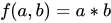
[edit]is the analytical representation of AND gate:




Alternatives
[edit]If no specific AND gates are available, one can be made from NAND or NOR gates, because NAND and NOR gates are "universal gates" [1] meaning that they can be used to make all the others.
| Desired gate | NAND construction | NOR construction |
|---|---|---|
 |  |  |
AND gates with multiple inputs
[edit]AND gates with multiple inputs are designated with the same symbol, with more lines leading in.[2] While direct implementations with more than four inputs are possible in logic families like CMOS, these are inefficient. More efficient implementations use a cascade of NAND and NOR gates, as shown in the picture on the right below. This is more efficient than the cascade of AND gates shown on the left. [3]
 A 12-input AND gate realized as a cascade of AND gates
 12-input AND gate made from 3 NAND and 1 NOR gate


See also
[edit]
References
[edit]- ↑ Mano, M. Morris and Charles R. Kime. Logic and Computer Design Fundamentals, Third Edition. Prentice-Hall, 2004. p. 73.
- ↑ "Multiple-input Gates". All About Circuits. Retrieved 2024-02-04.
- ↑ Norman Hendrich. "AND gate (12 inputs)". Universität Hamburg. Retrieved 2024-02-04.
Common logical connectives | ||
|---|---|---|
 | ||


