


Conjugate beam method
.png)
The conjugate-beam methods is an engineering method to derive the slope and displacement of a beam. A conjugate beam is defined as an imaginary beam with the same dimensions (length) as that of the original beam but load at any point on the conjugate beam is equal to the bending moment at that point divided by EI.[1]
The conjugate-beam method was developed by Heinrich Müller-Breslau in 1865. Essentially, it requires the same amount of computation as the moment-area theorems to determine a beam's slope or deflection; however, this method relies only on the principles of statics, so its application will be more familiar.[2]
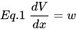
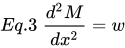
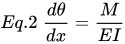
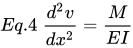
The basis for the method comes from the similarity of Eq. 1 and Eq 2 to Eq 3 and Eq 4. To show this similarity, these equations are shown below.
Integrated, the equations look like this.

![{\displaystyle M=\int \left[\int w\,dx\right]dx}](https://wikimedia.org/api/rest_v1/media/math/render/svg/1432da69bff134a4f9193ff443b543110f802458)
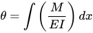
![{\displaystyle v=\int \left[\int \left({\frac {M}{EI}}\right)dx\right]dx}](https://wikimedia.org/api/rest_v1/media/math/render/svg/fe6ad3f431f994f985d66a61319285567e0c42fd)
Here the shear V compares with the slope θ, the moment M compares with the displacement v, and the external load w compares with the M/EI diagram. Below is a shear, moment, and deflection diagram. A M/EI diagram is a moment diagram divided by the beam's Young's modulus and moment of inertia.
To make use of this comparison we will now consider a beam having the same length as the real beam, but referred here as the "conjugate beam." The conjugate beam is "loaded" with the M/EI diagram derived from the load on the real beam. From the above comparisons, we can state two theorems related to the conjugate beam:[2]
Theorem 1: The slope at a point in the real beam is numerically equal to the shear at the corresponding point in the conjugate beam.
Theorem 2: The displacement of a point in the real beam is numerically equal to the moment at the corresponding point in the conjugate beam.[2]
Conjugate-beam supports
[edit]When drawing the conjugate beam it is important that the shear and moment developed at the supports of the conjugate beam account for the corresponding slope and displacement of the real beam at its supports, a consequence of Theorems 1 and 2. For example, as shown below, a pin or roller support at the end of the real beam provides zero displacement, but a non zero slope. Consequently, from Theorems 1 and 2, the conjugate beam must be supported by a pin or a roller, since this support has zero moment but has a shear or end reaction. When the real beam is fixed supported, both the slope and displacement are zero. Here the conjugate beam has a free end, since at this end there is zero shear and zero moment. Corresponding real and conjugate supports are shown below. Note that, as a rule, neglecting axial forces, statically determinate real beams have statically determinate conjugate beams; and statically indeterminate real beams have unstable conjugate beams. Although this occurs, the M/EI loading will provide the necessary "equilibrium" to hold the conjugate beam stable.[2]
| Real beam | Conjugate beam | ||
|---|---|---|---|
| Fixed support |  |
Free end |  |
|
|
| ||
| Free end | |
Fixed support | |
|
|
| ||
| Hinged support |  |
Hinged support | |
|
|
| ||
| Middle support |  |
Middle hinge |  |
|
| ||
| Middle hinge | |
Middle support | |
|
| ||


| Real beam | Conjugate beam | |
|---|---|---|
| Simple beam |  |
|
| Cantilever beam | .svg) |
.svg) |
| Left-end Overhanging beam |  |
 |
| Both-end overhanging beam |  |
 |
| Gerber's beam (2 span) | .svg) |
.svg) |
| Gerber's beam (3 span) | .svg) |
.svg) |
Procedure for analysis
[edit]The following procedure provides a method that may be used to determine the displacement and deflection at a point on the elastic curve of a beam using the conjugate-beam method.
Conjugate beam
[edit]- Draw the conjugate beam for the real beam. This beam has the same length as the real beam and has corresponding supports as listed above.
- In general, if the real support allows a slope, the conjugate support must develop shear; and if the real support allows a displacement, the conjugate support must develop a moment.
- The conjugate beam is loaded with the real beam's M/EI diagram. This loading is assumed to be distributed over the conjugate beam and is directed upward when M/EI is positive and downward when M/EI is negative. In other words, the loading always acts away from the beam.[2]
Equilibrium
[edit]- Using the equations of statics, determine the reactions at the conjugate beams supports.
- Section the conjugate beam at the point where the slope θ and displacement Δ of the real beam are to be determined. At the section show the unknown shear V' and M' equal to θ and Δ, respectively, for the real beam. In particular, if these values are positive, and slope is counterclockwise and the displacement is upward.[2]
See also
[edit]References
[edit]- OKAMURA Koichi岡村宏一 (1988). Kouzou kougaku (I) Doboku kyoutei sensyo. Kashima syuppan. ISBN 4-306-02225-0.
- ↑ Bansal, R. K. (2010). Strength of materials. ISBN 9788131808146. Retrieved 20 November 2014.
- 1 2 3 4 5 6 Hibbeler, R.C. (2009). Structural Analysis. Upper Saddle River, NJ: Pearson. pp. 328–335. ISBN 9780136020608.
- 1 2 Okmamura (1988)、p.171。
| Dynamic analysis | |||||||
|---|---|---|---|---|---|---|---|
| Static analysis | |||||||
| Structural elements |
| ||||||
| Theories | |||||||
